
CNC Router Online Help and Troubleshooting Guide
Machine Doesn't Move Scenario:You are repeatedly getting one of the following two message boxes: 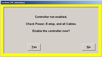 or
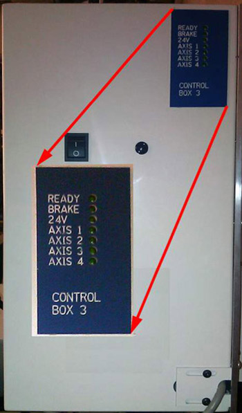
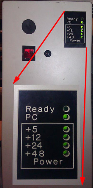
or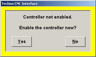 Problem: The Emergency stop loop has been tripped or the machine is not connected. Solution: Ensure the Emergency Stop Switches are disengaged by pressing them in and then rotating them out. Then try to enable the controller again.  If the problem persists: If your control box has a ready light, while watching the ready light, click to enable the controller. The exact moment you click to enable, the ready light may blink. You may need an assistant to click to enable while you watch the ready light.
Note that your control LED badge may be blue and labeled with different text. The ready light is the only important LED for this test.
If the ready light blinks one time like this (this video cycles every 10 seconds, be patient): If the problem persists: If your control box has a ready light, while watching the ready light, click to enable the controller. The exact moment you click to enable, the ready light may blink. You may need an assistant to click to enable while you watch the ready light.
Note that your control LED badge may be blue and labeled with different text. The ready light is the only important LED for this test.
If the ready light blinks one time like this (this video cycles every 10 seconds, be patient):
|
The problem is the E-stop loop. Note that the E-stop loop runs through not only the emergency stop switch, but all of the motors as well. This is done to prevent a dangerous situation.
|
|
Estop loop broken Scenario: The ready light is blinking on the controller when the user attempts to enable, but the emergency stop is not the cause. The following screen persists: |
|
or Problem: The Emergency stop loop has been tripped. The emergency stop loop is run through all of the motors as well as the E-stop button. It must be determined which segment of the E-stop loop is broken. Solution: Before doing any work on the machines, switch off and lock out power to the control box.
›Check all cables going into the control board inside the control box. Ensure they are completely engaged and screwed in tightly. If the problem persists, you will next need to isolate the problem. Find the jumper block on the control board. (Determine your Controller box) |
LC Plus Control Board E Stop Jumper header 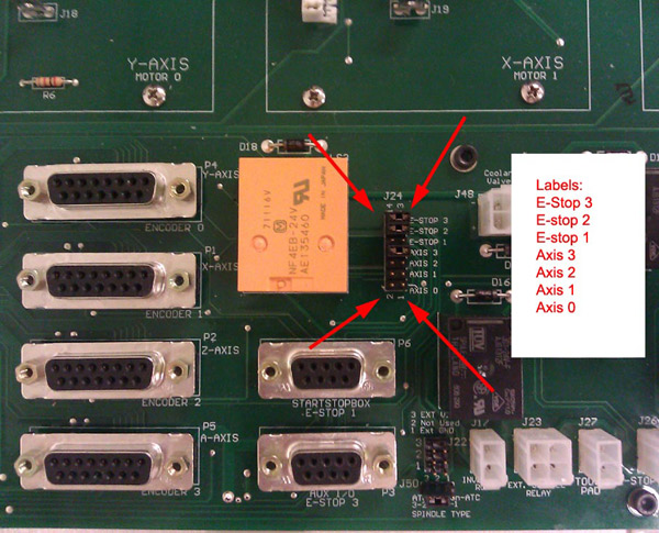 |
LC Control Board E Stop Jumper header 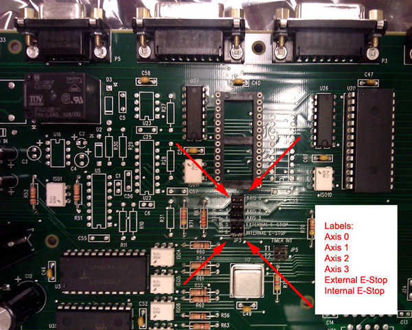 |
If the jumper removed was for an Emergency Stop, inspect the wiring inside the Emergency stop box. It is likely loose or broken. After repairing the problem, be sure to restore the original state of the jumpers. You may be tempted to run the machine with all of the jumpers in place instead of fixing the cause of the problem. Note that this is a dangerous practice, as the machine cannot sense lost feedback and could result in an extremely high speed runaway axis. If you are unable to locate the cause of the E-stop problem, contact tech support. |
|
Estop noblink Scenario: The ready light is not blinking while attempting to enable the controller. Controller box Your machine is using the LC Plus controller or a Premium Class controller. It is NOT a low power LC or LP controller. You receive one of the two following error boxes:
orProblem: The machine is not connected to the PC, or the controller cable is damaged. Solution:
If the ends are secure and the problem still occurs:
|
| Estop no ready light Scenario: The machine is not enabling, and the controller is one which does not have a ready light indicator. Controller_box Your machine is using the LC Plus controller or a Premium Class controller. It is NOT a low power LC or LP controller. You receive one of the two following error boxes:
orProblem: The machine is not connected to the PC, or the controller cable is damaged. Solution:
|
| Locking out power: Locking out power prevents the machine from harming the user while the machine is being worked on. Dangerous voltages and the potential for the machine to move will exist if the machine is powered up while it is being serviced. NEVER WORK ON OR INSIDE A MACHINE THAT IS POWERED UP OR HAS THE POTENTIAL TO BE ACCIDENTALLY POWERED UP The regulations at your workplace may vary from standard regulatory requirements. When conflicting regulations are encountered, follow your workplace regulations. If there is ANY uncertainty, contact your workplace supervisor. Locking power out from a machine is required for any servicing. Power down the machine and the computer by the normal methods. Remove the power source from the machine and lock it out as per your workplace regulations. This may involve an actual lock on a breaker box, a nametag, or some similar methods. Many machines have multiple sources of power (control box, spindle, etc). Be sure to find all power sources and lock all of them out prior to any service. Scenario: You are repeatedly getting the following message box: 
Problem: The machine is unable to travel to the position that has been requested of it. Solution: There are a few pieces of information necessary to determine the cause of this issue.
If the machine does not move in any of the axes, you should Verify power to the machine
• Verify power to the machine • Ensure feedback in setup • Are you attempting to move the system at a speed higher than possible for the Controller box? • Is the machine smashing into the End of travel? • Is there a blockage in the axis that is causing a Frozen axis? • Check for Amplifier status. • If the symptom of the position error is that it only occurrs in a specific location on the machine, you can test for Axis tightness. This is very uncommon. Run away: Scenario
Problem: The encoder feedback data is not reaching the controller.
|
| Verify Power: To verify power to the machine, you must first ascertain which Controller box you are using. LC / LP Controller box: > Check the diagnostic LEDs on the front. If PC is lit and no other LEDs are lit, the controller box is not receiving any external power. Verify the Power switch is on. Verify the power cable is plugged in and the outlet it is plugged into is live. Check the fuses in the Power receptacle. If the PC, +5, +12, +24 lights are lit (ready is irrelevant in this scenario) and the +48 is not lit, the motor fuse inside the control box is blown. After performing Lock out power, replace the fuse with 5x20mm 10A 250v cartridge fuse. LC Plus Controller box: > Check the diagnostic LEDs on the front. If the 24v LED is not lit, the controller box is not receiving any external power. Verify the Power switch is on. Verify the power cable is plugged in and the outlet it is plugged into is live. Check the fuses in the Power receptacle. Servo Box 1,2: > If the fan is not blowing in the back of the controller box, the controller box is not receiving any external power. Verify the Power switch is on. Verify the power cable is plugged in and the outlet it is plugged into is live. Check the fuses in the Power receptacle. |
| Ensure feedback in setup: To verify the system is communicating with the controller properly:
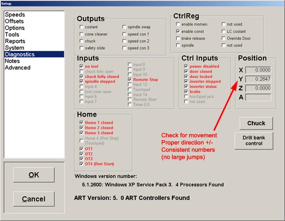 If all connected axes show proper and consistent feedback, then the connection is likely good. If only some axes provide feedback: |
| Controller box: The controller box encloses the control electronics, and provides a safe environment. There are many ways to determine which controller your machine employs. Note that this list is not exhaustive. Older and less common controllers are not listed here. If you do not see your controller here, obtain any part numbers or markings before contacting support. *If possible, take a picture of the controller and email it to tech support. Types Of Controllers |
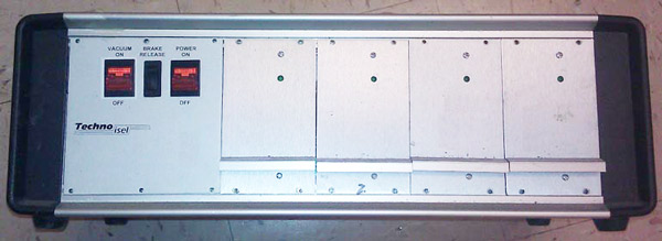
| LC Plus Controller
This is the current LC Plus control box. Note the Blue badge. This controller is frequently referred to as:
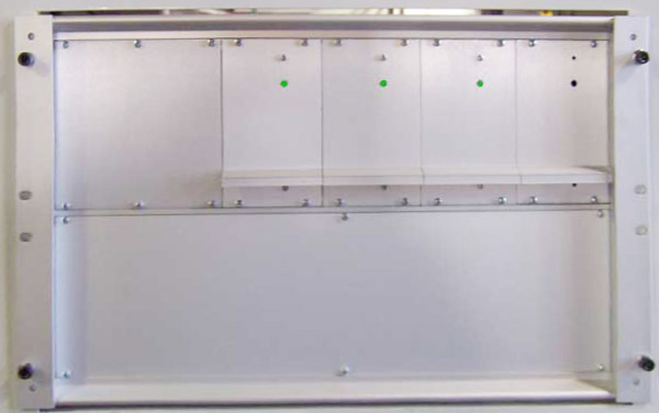
 |
This is the current LC Plus control board inside the box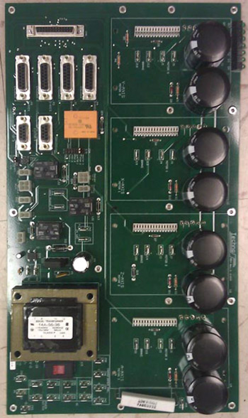 This is the PCI Card that will be inside the PC 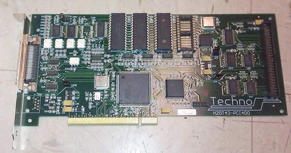 |
LC Control Box This is the current LC (AKA LP) control box. Note the Black badge. This controller is frequently referred to as:
 This is the current LC control board inside the box. 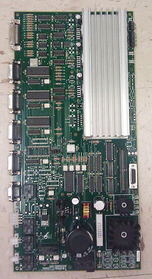 This is the PCI Card that will be inside the PC. 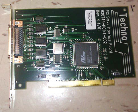 |
Servo Box 1 This is the current MP Control Box This controller is frequently referred to as:
 This is the PCI Card that will be inside the PC. NOTE: It is the same card as some other controllers. Servo Box 2 This is the current MP Control Box This controller is frequently referred to as:
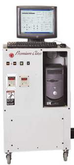
 This is the PCI Card that will be inside the PC. NOTE: It is the same card as some other controllers. Premium Controller This is the Premium Class console. This controller is frequently referred to as:
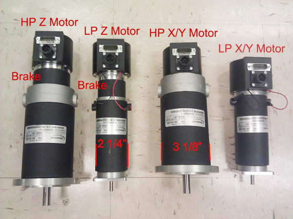
 This is the PCI Card that will be inside the PC. NOTE: It is the same card as some other controllers. *You may also narrow down your controller type by the type of motor it is using. Note that this will not necessarily result in a perfect match.
For reference, note the ratio of the size of the encoder housing (aluminum tube with the cables in the back) to the motor body.
 |
| Power receptacle: The power receptacle is located at the back of the box. 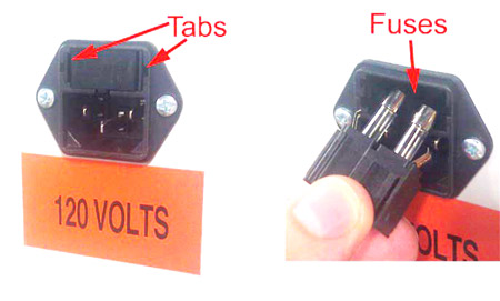 It will have the power cable running into it.
Multimeter: This is a picture of a multimeter. Yours may look different, but the important symbols should be the same. 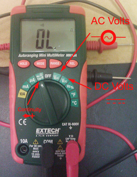 |
Setting the origin For proper operation, the machine has to "match" up the coordinate system with that of the drawing that it is running. The origins are sometimes referred to the zeroes. Do not confuse this position with the home, which is a the end of travel of all of the axes. The origin of the material is typically at one of the corners of the part. Sometimes it is in the middle of the part. Common to cabinet making and some other woodworking applications where stock isn't flat and veneers are involved, the Z zero is at the bottom of the material. The origin of the part in the CAM software relative to the material must match the origin of the machine relative to the material in the real world. If these origins do not match, the part will not be cut properly. To set an origin, jog the machine to where the origin is and click Zero on the interface and then All. To quickly set the origin for the Z axis only, use the touchpad by placing the touchpad on the surface that is to be Z zero, hovering above the pad, and clicking Tool, then Touch off Z zero. Note that this will not set the X and Y zero. To adjust the origins by a set amount without moving, double-click the origin readout in the upper right of the interface and enter values by which to move the origin around. This is especially useful for moving the origin to a spot that is not physically achievable. |
A frozen axis is one that will not move by way of the controller, and cannot be manually moved by the user when the machine is powered down. Scenario:
Problem: The ball nut is possibly jammed-up with debris. This is especially likely if the machine is used to cut wood or other material that easily becomes airborne after being cut. Solution:
|
It may be necessary to check to see if an amplifier is enabling. First, find your Controller box. On the LC Plus control box:
|
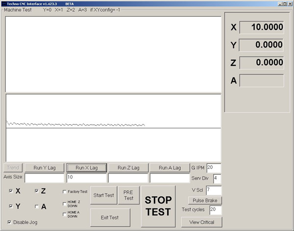
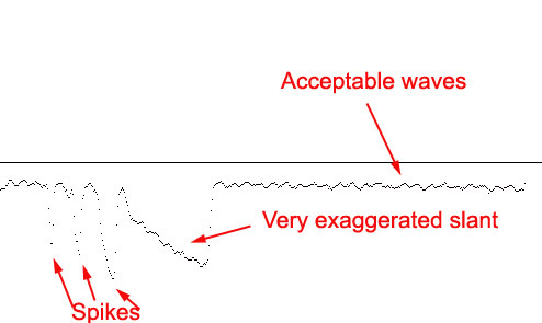
In rare circumstances, one of the axes may suffer from tightness in only certain spots. To find this tightness, there is an axis lag test that can be run. This test is available in 1.421.10 and higher.
 |
Niniejsza lekcja gry w pi?k? tanie koszulki pi?karskie no?n? przedstawia, ?wiczy i testuje 10 pi?karskich s?ów zwi?zanych Kup tanie koszulki pi?karskie ze strojami. Nasz szeroki wybór ró?nych artyku?ów odzie?owych Koszulki koszykarskie obejmuje szorty, skarpety, t-shirty, a nawet specjalistyczn? koszulka baseball M?ska bielizn?. Ubrania s? zbiorowym okre?leniem przedmiotów noszonych na ciele. Odzie? mo?e by? wykonana koszulki rowerowe z tkanin, skóry zwierz?t lub innych cienkich arkuszy materia?ów razem wzi?tych. Zapoznaj si? z nasz?xn--odziesportowa-74c.com najnowsz? odzie?? damsk?. Zaktualizuj swój wygl?d dzi?ki butykoszulkipolo.com najnowszym produktom sezonowym.
Copyright ©
Techno CNC Systems, LLC. All rights reserved.