|
An inverter is an electrical device that converts direct current (DC) to
alternating current (AC). It may be single phase or 3 phase, and powers the
machine’s systems and motors. It is so named because early mechanical AC to DC
converters were modified and made to work in reverse, and thus were "inverted",
to convert DC to AC.
Inverter Basics
Inverters usually need to be programmed with values obtained from the
name plate on the spindle (get pic) of the machine into which the
inverter is to be installed.
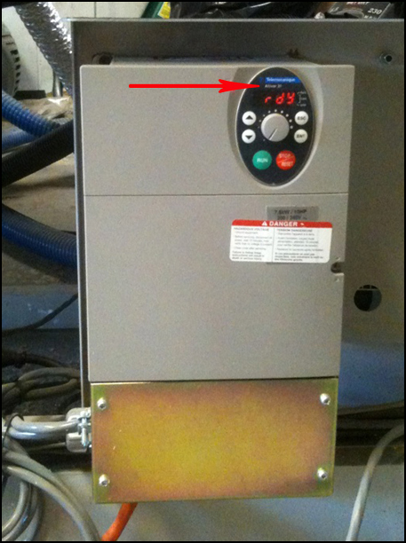
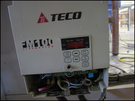
Shown here are 2 inverters, an Altivar 31 (note that it says "Altivar 31"
below the blue Telemechanique Logo). The second inverter is a Teco FM100, which
we no longer use though you may still encounter these. Important considerations
in replacing inverters are:
- Phase (single phase or 3 phase?)
- ATC (does machine have an automatic tool changer?)
- Horsepower
- Voltage
- Amperage
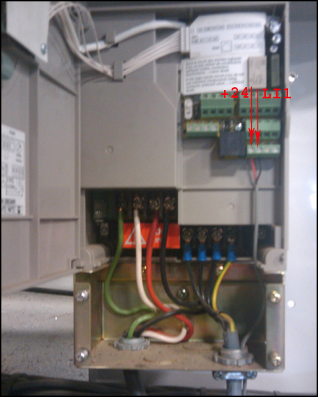
To test spindle, short the screws marked " +24V " and " LI1 "
, the small red and black wires above
To change the direction of spindle rotation, swap any 2 of the 3 power
wires that go from the inverter to the spindle (excluding the green/ground!).
These wires are usually but not always on the right side. Consult a licensed
electrician.
In some setups, the Inverter may be located somewhere other than on the
machine, such as on a wall, as in this case: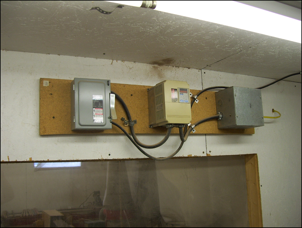
Part Numbers for Telemechanique Altivar 31
Electronics Part Number
- 05 HP/230v = H24Z40-IV5HP230V
- 10 HP/230v = H24Z40-IV10HP230
- 15 HP/230v = H24Z40-IV15HP230
- 05 HP Inverter Conduit Box = H24M10-VW3A31815
- 10 HP Inverter Conduit Box = H24M10-VW3A31816
Programming Inverters
Required Tools
- Serial-to-RJ45 cable
- PowerSuite application
- Power leads
Quick Method
- Connect serial-to-RJ45 cable
- Start PowerSuite
- Click " i " button
- My Configurations
- Altivar Drives
- ATV31
- Find your inverter on the list
- Right-click + Download
- Alt-F at warning
- Click OK
If that method failed, try the longer method.
Alternate (Long)
method
- Follow above steps
- (highlight)My Device
- Click "Connect the Device" button on toolbar
- Ingnore warning
- Explorer menu:
- Motor Control
- Motor Characteristics
- Input values from Spindle plaque
- Adjustments
- Accel / Decel
- Accel should be 2 or more. this is the acceleration rate.
- Decel should be 0.5 This is set to a very low value
because adaptive deceleration is used. You may try increasing the value
of this. I would probably not use a value greater than 3.0. The larger
the value, the longer it will take for the spindle to stop.
- SdC = 0.5
- brA = Yes
- Frequency range
- TFR (first)
- HSP = 300 - This is the maximum frequency.
- LSP = 100
- ITH = set this to the current on the nameplate
- Thermal Protection - use Amperage value from spindle plaque
- Optimization
- Set voltage boost = 0
- UFT = Constant
- Application Functions
- Preset speed values
- SP2
- 100
- 133
- 166 etc.
Programming thru Inverter Funtion Buttons
The Inverter's programming can be adjusted by the user via the function
buttons on the inverter itself. Please contact Technical Support for help with
these functionalities.
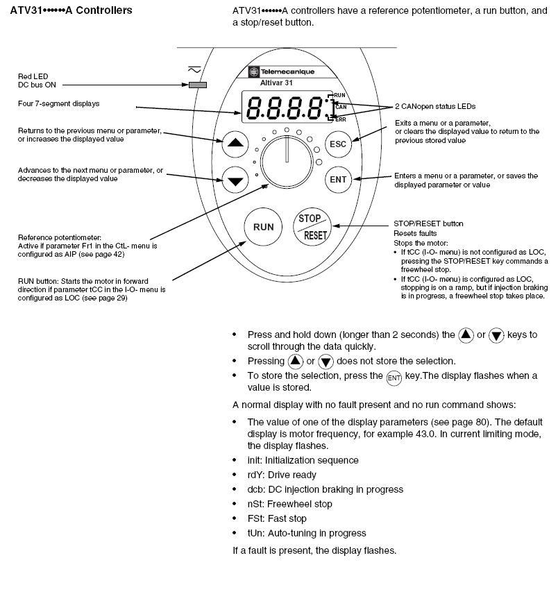
-
- from drC menu :
-
- tFr - 300 set this BEFORE setting HSP and LSP.
- From the set menu:
-
- ACC - this may be set between 0.5 and 3 this is the
acceleration rate.
- DEC 0.5 - This is set to a very low value because adaptive
deceleration is used. You may try increasing the value of this. I would
probably not use a value greater than 3.0. The larger the value, the
longer it will take for the spindle to stop.
- LSP - 100
- HSP - 300 This is the maximum frequency
- ITH - set this to the current on the motor nameplate.
- from drC menu :
-
- Un5 - set this to the voltage indicated on the motor
nameplate.
- FR5 - 300
- nCr - set this to the current indicated on the motor
nameplate.
- nSP - 18.00
- COS - this is the motor power factor as indicated on
the motor nameplate. It could be 0.8 for your spindle
- UFT - constant (the option to choose is "L")
- tFr - 300
- From the I-O menu: - you shouldn't have to change this, this
only affects the on/off control signal to the spindle
-
- tCC - 2C
Remember to press "Enter" after each entry is made to save the entered value.
- Save Configurations:
- drC menu > SCS > Str 1
|


